FER/Solid
- A finite element program of solid and structure mechanics interfaced
with CAD programs
The program FER/Solid can
be interfaced with other finite element software or CAD programs.
The main features include :
- CAD to FEA
- only nodes and elements are necessary
for the preprocessing,
- freind GUI - Graphical User Interface
- easy operation about the definition
of material properties, selection of nodes, elements, boundary lines or
surfaces elements for the definition of boundary conditions,
- static stress analysis of 2D or
3D solids and structures,
- modal analysis (natural frequences
and mode shapes) of structures,
- powerful postprocessing.
The following figures illustrate the link between FER/Solid
and Pro/Engineer (as example). Three general steps are performed
for a typical stress analysis.
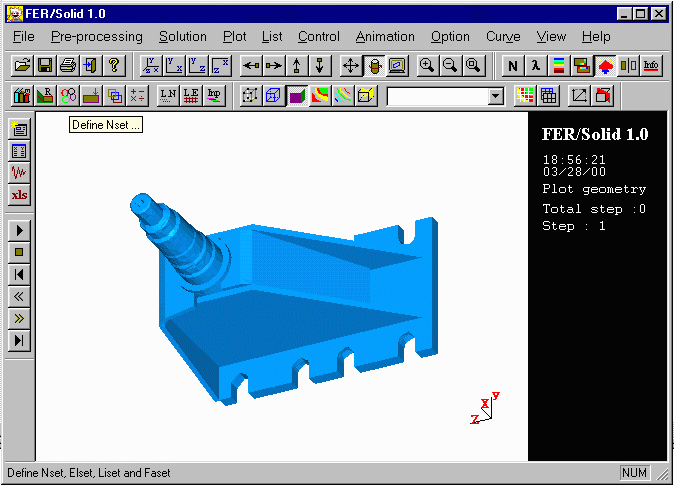
- Preprocessing : The model
geometry and the mesh are created by Pro/Engineer. Then, FER/Solid
imports directely the model (Figure 1).
It allows to define the element types, element real constants, material
properties.
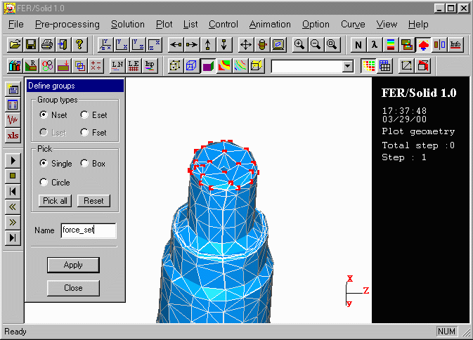
- Solution : We apply loads
and boundary conditions to the selected groups (nodes, elements) and obtain
the solution (static or modal solution). (Figure 2)
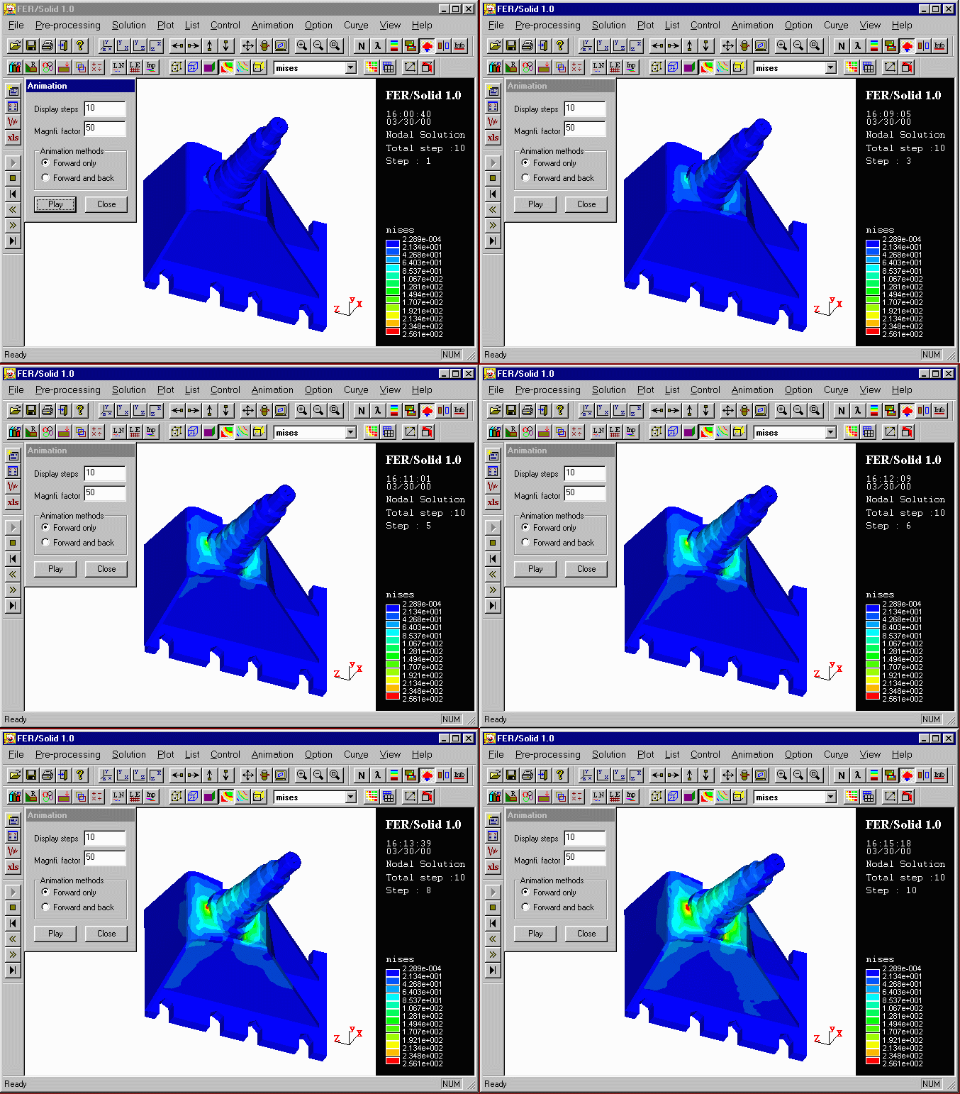
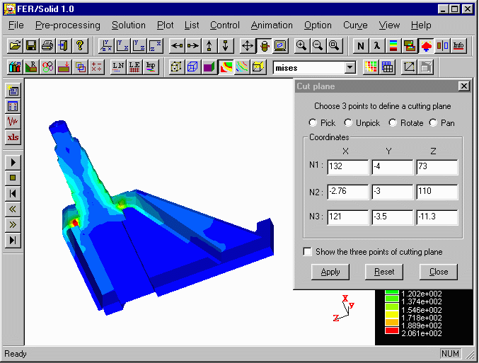
- Postprocesing : Results
display and presentation with a powerful postprocessor (see also FER/View
2.0 ). (Figure 3: Mises stress coutours;
Figure 4: cut plane display for an inside view).

Figure 1 : Pro/Engineer
to FER/Solid (nodes : 6631, elements : 22554)

Figure 2 : Boundary conditions definition by using
some useful tools (Zoom, Rotation, Box picking etc.)

Figure 3 : Mises stress
coutours (animation plot)

Figure 4 : Cut plane display
for an inside view
 Return
to principal page


